Looking for more information on USB drive technology? Try these links:
Wikipedia Flash Entry
en.wikipedia.org/wiki/Usb
Encyclopedia
USB Implementers Forum
www.usb.org
USB Implementers Forum
Custom USB Drives
usbmemorydirect.com
Wholesaler
|
Looking for more information on USB drive technology? Try these links: Wikipedia Flash Entry USB Implementers Forum Custom USB Drives |
   |
||||||||||||||||||||||||
Welcome to the very best USB flash memory drive facts site on the webHere at USB-facts.com, our goal is to inform people about Universal Serial Bus technology and history, while also providing updates on news in the USB and Flash Memory world. What is USB?USB isn't reserved just for those nifty little hard disks that store data. The term actually stands for Universal
Serial Bus, which is a serial bus standard. It was mainly developed to interface peripheral devices into one standard port
and to allow fast on-the-go connection without rebooting, also known as plug-and-play. Another feature is that it provides power
to peripherals. For example, iPods, PDAs, keyboards, and mouse devices, to name just a few. In more recent years, it has been adopted by major computer manufacturers and is now a standard sight on most personal computers. USB has been standardized over the years by the Implementers Forum (USB-IF), which is a joint standards body comprised of major companies in the computer and electronics industries. Some of the well known names are Apple, Hewlett-Packard, NEC Corporation, and many others. The History of Universal Serial BusThe technology first came about in 1995 with the introduction of its 1.0 standard. It had a few high ranking early promoters - mainly the big software and hardware companies such as Intel, Microsoft, and Philips. However, it did have difficulty lifting off, having to compete with another up-and-coming serial bus standard. Firewire, created in 1990 by Apple, was technologically superior and development was completed in 1995 with much higher transfer rates than its counterpart, Universal Serial Bus. Although Firewire was a faster serial bus, Apple and other developers demanded royalty fees from the end-user systems (25¢ and $1-2 for more expensive hardware). On top of the royalty fees, USB had another advantage over Firewire which piqued the interest of the major CPU manufacturers - it relies on the end-users core speed. The next update to USB was made in 1998, USB 1.1, which was a patch to fix a few of the bugs associated with the first release. Currently, we are using the USB 2.0 standard which was released in April of 2000, turning into the standard by the end of 2001. The 2.0 standard is backwards compatible with all other renditions of 1.0 and 1.1. It is also compatible with all previous versions of 2.0 standard. In the future, USB 3.0 is said to arrive in late 2009 or early 2010. How Does It Work?You may be asking yourself, "How exactly does my computer send data to a flash drive and how does it even know that a device is plugged in?" When you first turn on your computer, it scans all your USB ports for devices and assigns them addresses. This process is called "enumeration". After initially scanning additional devices that are plugged into a port such as a mouse, keyboard, or Flash Disk, these are also enumerated. Along with the process of enumeration, the host machine also determines what type of data transfer will be used by each USB device. There are three different types of data transfer listed below.
After enumerating the USB ports and determining what type of data transfer will be used, the host will begin to allocate bandwidth. Isochronous and Interrupt use up to 90% of the 480mbps bandwidth after 90% has been reached. The host denies any additional bandwidth use to USB ports of those two types. The left over bandwidth, which is a minimum of 10%, is used by Bulk transfers and host control packets. Data is sent out every millisecond to the USB devices in what is called a frame. Frames are 1500 byte in size. Again Isochronous and Interrupt receive first priority of bandwidth and bulk uses the remainder which is no less then 10% of the 480mbps. Types Of Connections
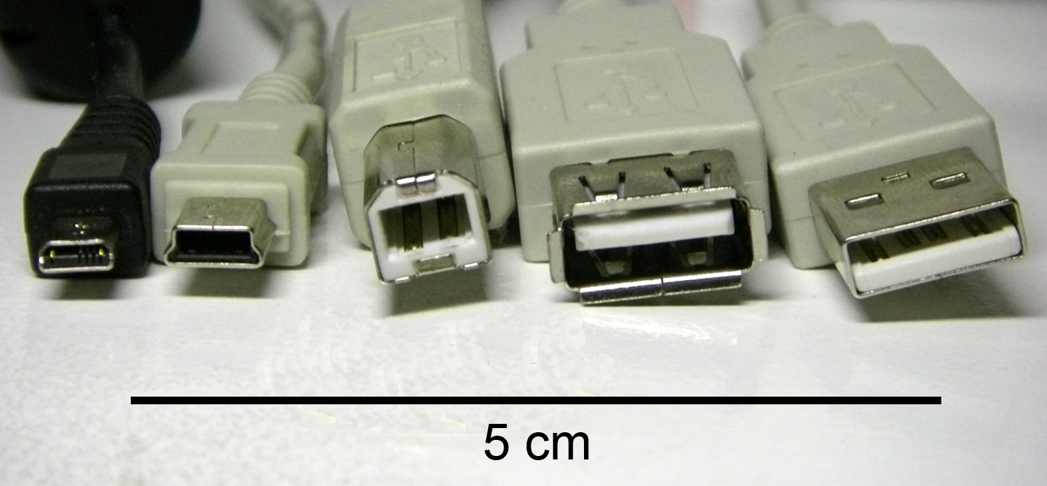
There are currently 4 different types of USB connectors, each with respective receptacles. The original specification included two: Standard-A and Standard-B USB plugs. Today, the most popular and most recognizable USB plug is the Standard-A. Standard-B is mostly used for printers, scanners, and copiers. The first noticeable change to USB when USB 2.0 was launched was the addition of Mini-B plugs and receptacles. Mini-B USB plugs are most commonly associated with smartphones and PDA's. USB-IF announced Micro-USB on January 4, 2007. The Micro-USB is meant to replace Mini-USB for use with smartphones and PDA's. USB-IF has already made plans to introduce Micro-A plus, Micro-AB Receptacles, and Micro-B plugs and receptacles. Cable SpecificationsThere is a maximum length of 5 meters or ~16 feet. The reason for the limitation is that when the host machine sends a command, the maximum round trip delay is 1600ns. After reaching this, the command is considered lost. Longer USB cables cause lower voltages and signal quality below the limits of some devices. This lower quality and lower voltage may cause a USB device to function improperly or not at all. Another type of USB cable is the category 5 cable, also known as CAT5. These cables can extend USB communications up to 50 meters and USB transfers through fiber optics can reach up to 10km. Through the use of hubs or active extension cables, which are bus powered cables that extend the standard maximum length up to twice as much, they can reach greater lengths.
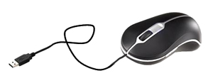
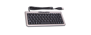
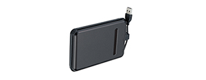
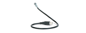
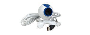
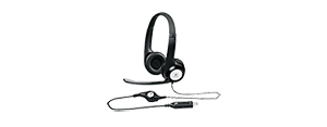
USB PeripheralsThere are a large selection of available devices which range from nearly every type of peripheral available for computers, as well as devices that are not necessarily used for computing. With a USB connection, peripherals can either integrate and be recognized within the operating system, or it can merely power a device, and as well combining both of these functions. This is a major reason why this standard has become so massively popular.
Some examples of peripherals would be:
Data Transfers in Flash Drives
All flash memory have a grid consisting of cells laid out in rows and columns. Each
cell represents one Bit these single bit cells can be binary 0 or 1. The flow of
current through the cells determines whether the cell is binary 0 or 1.
Each cell has a pair of transistors which are separated by a thin layer of oxide. The transistors are referred to as gates, one being the Control Gate and the other the Floating Gate. The thin layer of oxide holds electrons used to inhibit the flow of current from the floating gate to the control gate. The control gate is linked directly to the row, or wordline. The only link to the word line from the floating gate is through the control gate. While there is a link from the floating gate to the control gate the cell is binary 1. To alter the value of the cell electrons must be added or removed to create a 0 or 1, respectively, value. To do this a process known as Field Electron Emission is used to add electrons. A charge is applied to the floating gate typically ranging from 10 to 13 volts. The current flowing through the floating gate causes it to shoot of electrons trapping them on the other side of the thin strip of oxide. When the electrons are trapped behind the oxide strip they act as a barrier inhibiting the flow of current to the control gate diverting all the current through the floating gate to the cell sensor. The cell sensor measures the amount of current coming through the floating gate. If 50% or more of the current passing through the floating gate is picked up the cell has a value of 0. If less than 50% of the current passes through the cell has a value of 1. Power SpecificationsThe 1.x and 2.0 standards have a 5V supply on one wire where devices can get their power, which can have a range of 4.75V and 5.25V split within the negative and positive wired bus power. In USB 2.0, power made with low-powered hub ports can be 4.4V to 5.25V. A "unit load" is 100mA in USB 2.0, and will increase to 150mA with USB 3.0. There is a 5 unit load (500mA) maximum that can be accessed by a port with USB 2.0, while it is increased to 6 unit loads (900mA) for USB 3.0. Two types of devices exist, both low-power and high-power. With low-power devices, these pull 1 unit load maximum and have a minimum operating voltage of 4.4V for USB 2.0, while it is lowered to 4V for USB 3.0. A high-power device can pull the maximum unit loads allowed by the standard used. Each device will default to low-power, however the software for the device can ask for high-power, provided that the power is accessible for the bus being used. Bus-powered hubs start at a 1 unit load, shifting to a maximum unit load once hub configuration is complete. All devices plugged into the hub will draw a 1 unit load, unaffected by any devices attached to other ports of the hub. Self-powered hubs will provide the maximum allowed unit loads to any device which is connected. For battery-powered hubs, it is possible to provide the maximum unit loads needed by any connected ports. Additionally, the VBUS can supply 1 unit load upstream for communication purposes if parts of the Hub are not currently being powered. Many USB devices, such as an external hard drive, require much more power than could be provided by a single port. In this case, there may be a power supply that needs to be connected to the device for it to power on, or there may be a dual USB plug for pulling the additional power. USB devices are also designed to pull a limited amount of charge when first connecting the device in order to prevent any issues that might affect the computer's internal power. Some devices can be powered or charged by a portable adapter, which can be plugged either in a wall socket or car. Another option, Sleep-and-charge USB, is a type of port that can charge a device even if the computer system is shut off, but obviously still plugged in. |